



What you’ll learn
After this post, you will be able to calculate total resistance for a series circuit, and describe how voltage divides across series resistors.
One path, one current
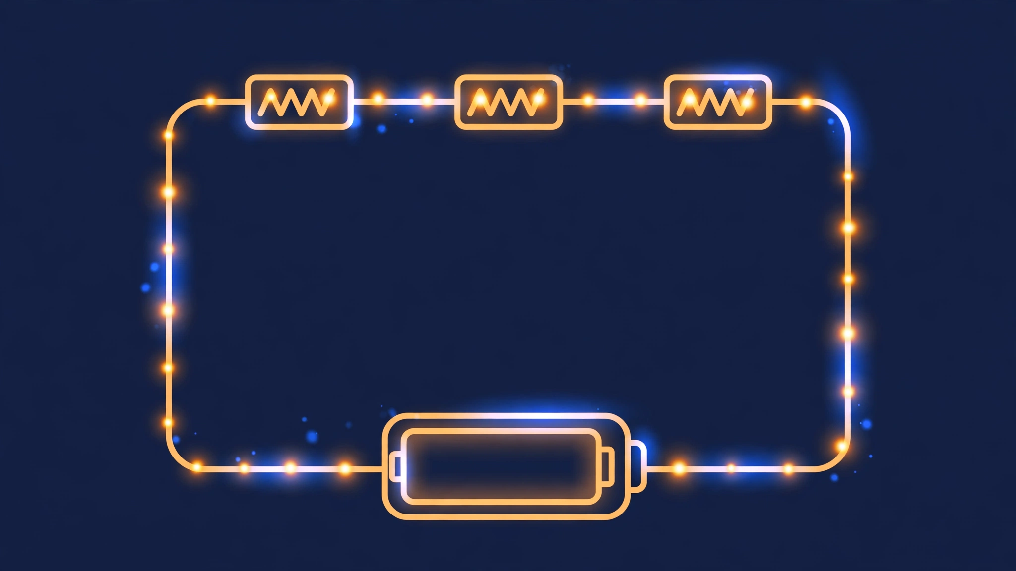
A series circuit has only one path for current. The same current flows through every component — through the first resistor equals through the second equals through the third. That single fact drives every series calculation in this post.
Total resistance adds up
In series, resistances simply add. Formula: RT = R1 + R2 + R3 + … Worked example from the handbook: three resistors of 10, 20, and 30 ohms in series give a total resistance of 60 ohms: RT = 10 + 20 + 30 = 60 ohms. Any number of resistors connected in series works the same way, and the total resistance is always greater than the largest single resistor. For a quick check: if one resistor is 850 ohms and the others are small, the total is just over 850 ohms, dominated by that one. Example: the handbook asks for the total resistance of a series circuit with resistors of 10 ohms, 20 ohms, 30 ohms — RT = 60 ohms. 60 ohms is the total of the three resistors, RT = R1 + R2 + R3 = 10 + 20 + 30 = 60 ohms. It is easy to get the right answer, but it is also easy to misread the question as asking for something else. Take the time to check what the question asks.
Total voltage adds up too
The total voltage of a series circuit is the sum of the voltages across each resistor. Formula: VT = V1 + V2 + V3 + … Applying the voltage-divider principle, each resistor’s voltage is proportional to its resistance: V1 = I × R1, V2 = I × R2, and the sum of the drops equals the source voltage.
Voltage drops: each resistor takes its share
The voltage across an individual resistor is called a voltage drop, or IR drop. Each drop reduces the source voltage as you trace the circuit. The largest resistor gets the largest drop; the smallest gets the smallest. Worked example: in a 120-volt series circuit with resistors 40, 60, and 100 ohms, total resistance RT = 200 ohms, current IT = 120 / 200 = 0.6 amps, and the drops are proportional: V1 = 0.6 × 40 = 24 volts, V2 = 0.6 × 60 = 36 volts, V3 = 0.6 × 100 = 60 volts. The drops add to 24 + 36 + 60 = 120 volts.
Common mistakes
- “In series, the current is different in each resistor.” It is not. One path means one current, the same through every component.
- “The voltage is the same across each series resistor.” It is not. The voltage divides in proportion to resistance; the largest resistor takes the largest share.
- “Voltage drops are losses you can ignore.” They are the circuit working: each drop is the voltage used by that resistor, and they always add up to the source voltage.
- “Total resistance in series is less than the smallest resistor.” That is parallel, not series. In series, the total is greater than the largest single resistor.
Summary
Series means one path and one current. Resistances add, voltages add, and each resistor takes a voltage drop proportional to its resistance. The total resistance is greater than the largest single resistor.
Quick-check questions
- What is the total resistance of 60, 100, and 150 ohms in series?
- In a series circuit, is the current the same through every resistor?
- A series circuit has 120 volts across 40, 60, and 100 ohms. What is the current?
- What are the voltage drops in that circuit, and what do they add up to?
- Does the total resistance of a series circuit end up larger or smaller than the largest single resistor?
Answers: 1. 310 ohms. 2. Yes — one path means the same current throughout. 3. Total resistance is 200 ohms, so the current is 120 / 200 = 0.6 amps. 4. 24 volts, 36 volts, and 60 volts, adding up to 120 volts. 5. Larger — the total is always greater than the largest single resistor.
Based on DOE-HDBK-1011/92, Electrical Science, Module 2, paraphrased for study.

Report a question

Top 10 Scorers
| Pos. | Name | Score | Duration |
|---|---|---|---|
| There is no data yet |

What defines a series circuit?
What is the total resistance of resistors of 60, 100, and 150 ohms in series?
What is the formula for total voltage in a series circuit?
Resistors of 50, 75, and 100 ohms carry 0.5 amperes in series. What is the total voltage?
What is a voltage drop, or IR drop?
A series circuit has 120 volts across 40, 60, and 100 ohms. What is the current?
In that same circuit, what is the voltage drop across the 60-ohm resistor?
What do the voltage drops in a series circuit add up to?
In a series circuit, which resistor takes the biggest voltage drop?
Is the total resistance of a series circuit larger or smaller than the largest single resistor?
