



What you’ll learn
After this post, you will be able to describe a voltage divider and a current divider, and calculate the voltage across part of a series network and the current in each branch of a two-branch parallel network.
Two shortcuts from Ohm’s Law
The last two posts covered series and parallel circuits in full. This post is the payoff: two shortcuts that technicians use daily, both of them just Ohm’s Law applied to those two patterns. A voltage divider gets different voltages from one source. A current divider splits current between two parallel branches without working out every branch from scratch.
Voltage divider: tap the series string
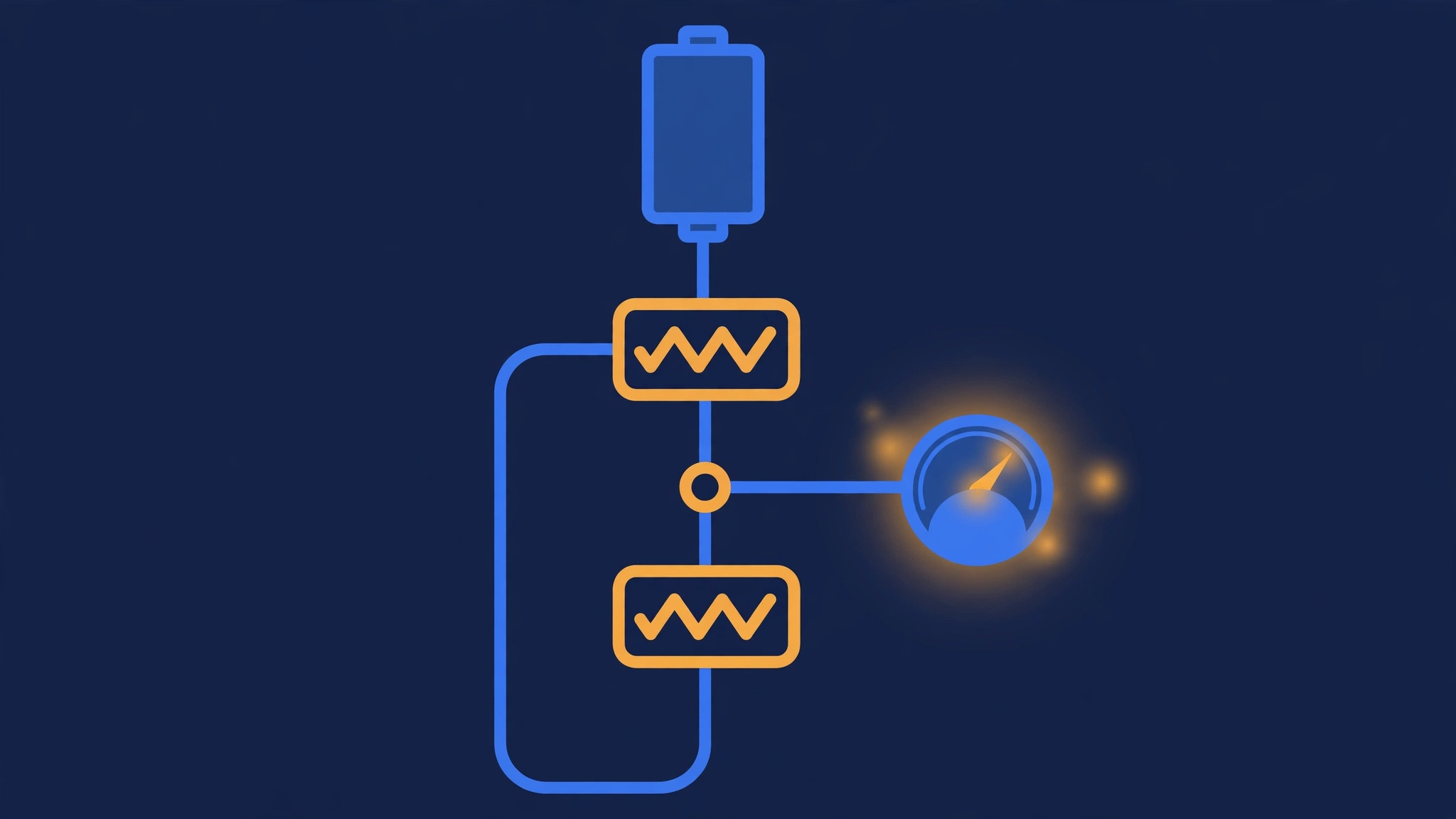
A voltage divider is a series network used to obtain different voltages from a single source. The series resistors divide the source voltage in proportion to their resistance: the drop across any resistor is the total current times that resistor’s value. In a three-resistor divider, the taps between resistors give three different voltages.
Worked example from the handbook: a voltage divider with a 24-volt source across resistors of 4, 8, and 12 ohms in series. Total resistance RT = 4 + 8 + 12 = 24 ohms, current IT = 24 / 24 = 1 amp. The drops are V1 = 1 × 4 = 4 volts, V2 = 1 × 8 = 8 volts, V3 = 1 × 12 = 12 volts, adding to 24 volts. Tapping across the first two resistors gives V = 4 + 8 = 12 volts; tapping across the last resistor gives 12 volts.
Current division: the opposite resistor decides
In a two-branch parallel circuit, the current divides in inverse proportion to the branch resistances. The formula is I1 = IT × R2 / (R1 + R2) and I2 = IT × R1 / (R1 + R2): each branch current uses the *opposite* resistor in the numerator. Worked example: total current 24 amperes, R1 = 6 ohms, R2 = 8 ohms. I1 = 24 × 8 / (6 + 8) = 192 / 14 = 13.7 amperes, I2 = 24 × 6 / 14 = 144 / 14 = 10.3 amperes, and 13.7 + 10.3 = 24 amperes.
When to use them, and when not to
Voltage dividers are for signals and reference voltages, not for efficient power delivery. The divider wastes power as heat in the resistors, and a load connected to a tap changes the division. Current dividers are for two-branch parallel circuits where you know the total current and the branch resistances. For more than two branches, work out each branch current with Ohm’s Law instead.
Common mistakes
- “In current division, the bigger resistor gets the bigger current.” It gets the smaller current. Current divides in inverse proportion to resistance.
- “A voltage divider gives me free extra voltages.” It gives you tapped voltages, but the divider wastes power and the tap voltage changes when you load it.
- “The voltage across a tapped part is the source voltage times the tapped resistance over the tapped resistance.” The divisor is the total series resistance, not the tapped resistance alone: V_tap = V_source × R_tap / R_total.
- “Current division works for any number of branches with the same formula.” The two-branch formula only works for two branches. For more branches, use Ohm’s Law on each branch.
Summary
A voltage divider is a series string with taps: each part takes a drop in proportion to its resistance. A current divider splits the total current between two parallel branches in inverse proportion to their resistances, with the opposite resistor in the numerator.
Quick-check questions
- What is a voltage divider used for?
- 24 volts across 4, 8, and 12 ohms in series — what is the current, and what are the drops?
- What voltage do you get tapping across the first two resistors in that circuit?
- In current division, which branch gets the bigger current?
- R1 = 6 ohms, R2 = 8 ohms, total current 24 amperes — what is the current in each branch?
Answers: 1. To obtain different voltages from a single source, using a series network. 2. Total resistance is 24 ohms, so the current is 1 amp; the drops are 4, 8, and 12 volts. 3. 12 volts. 4. The branch with the smaller resistance. 5. I1 = 13.7 amperes, I2 = 10.3 amperes.
Based on DOE-HDBK-1011/92, Electrical Science, Module 2, paraphrased for study.

Report a question

Top 10 Scorers
| Pos. | Name | Score | Duration |
|---|---|---|---|
| There is no data yet |

What is a voltage divider?
24 volts is applied across 4, 8, and 12 ohms in series. What is the current?
In that same circuit, what voltage do you get tapping across the first two resistors?
What is the voltage across one resistor in a series string, in terms of the source voltage?
In current division, how does the current split between two parallel branches?
What is the formula for the current in the first branch of a two-branch current divider?
R1 = 6 ohms, R2 = 8 ohms, total current 24 amperes. What is the current through the 6-ohm branch?
What do the two branch currents in a current divider add up to?
Why are voltage dividers not used for efficient power delivery?
If a load that draws significant current is connected to a voltage divider tap, what happens?
