



What you’ll learn
After this post, you will be able to identify the standard symbols for common electrical components, tell a schematic diagram from a pictorial diagram and a wiring diagram, and read a simple schematic by tracing the current path.
Why symbols matter
A circuit drawn as a photograph of real parts would be slow to draw, hard to read, and different every time. Symbols solve that. Every electrician, technician, and engineer reads the same shorthand: a zigzag for a resistor, a long and short line for a battery, a circle with a filament for a lamp. Learn the shorthand once, and you can read any circuit diagram in the trade.
The basic symbols
- Battery: one long line and one short line per cell, the long line positive, the short line negative. Several cells in series make a battery.
- Ground: a set of horizontal lines of decreasing length, like a small triangle made of lines, marking the earth or chassis reference point.
- Resistor: a zigzag line, or a rectangle in some standards. Its value is usually written beside it.
- Capacitor: two parallel lines, one straight and one curved in the handbook’s style, marking two plates separated by a dielectric.
- Inductor or coil: a series of loops, like a spring, marking a winding.
- Switch: a break in a line with a movable arm, open or closed. A single-pole single-throw switch is the simplest; it either completes the circuit or breaks it.
- Lamp: a circle with a filament loop inside.
- Fuse: a line passing through a small rectangle or a wavy line, marking a protective link that melts on overcurrent.
- Meter: a circle with a letter inside — V for voltmeter, A for ammeter, Ω for ohmmeter.
- Conductor: a plain line. Where two conductors cross without joining, one line jumps over the other or the crossing has no dot; where they join, there is a dot at the crossing.
Three kinds of diagram
- Schematic diagram: shows the electrical connections and the function of the circuit, using symbols. It does not show where parts physically sit.
- Pictorial diagram: shows the components as they actually look and where they sit, useful for assembly and for finding parts.
- Wiring diagram: shows the actual wires, their colours, and their terminal points, useful for installation and for finding a fault.
The handbook’s rule of thumb: use the schematic to understand, the wiring diagram to build and find faults, and the pictorial diagram to see what it looks like. A labelled diagram, in the handbook’s method, carries one main symbol and a short line of lettered points — for example, a lamp drawn with numbered filaments — but the circuit as a whole is still read as individual symbols.
How to read a schematic
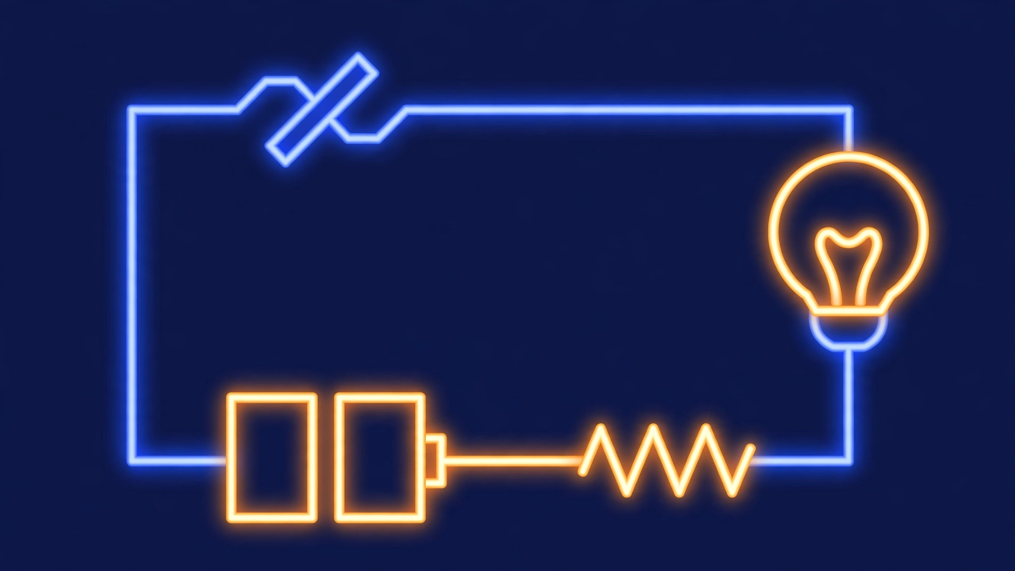
Start at the source — the battery or supply — and trace the current path through each component back to the source. Note the switches: are they drawn open or closed? Note the resistors: are they in series or in parallel? And note any meters: a voltmeter connects across a component and draws almost no current; an ammeter connects in series and measures the current flowing. The handbook gives a worked example: a simple circuit with battery, switch, resistor, and lamp. With the switch open, no current flows and the lamp is dark. Close the switch, and current flows through the resistor and the lamp. If the lamp does not light, check the fuse first — it is the protective link — then check for a broken conductor or a failed switch, working along the path.
Common mistakes
- “The diagram shows where the parts physically are.” A schematic does not. It shows how they connect, not where they sit. Use a pictorial or wiring diagram for layout.
- “Two lines crossing means they are connected.” Not unless there is a dot at the crossing. Without a dot, the wires pass over each other without joining.
- “A longer line in a battery symbol is the negative.” It is the positive. The short line is negative.
- “A schematic with a switch drawn open means the circuit is broken forever.” It means the switch is off at that moment. Close it, and the circuit should work.
Summary
Symbols are the shorthand of the trade: battery, ground, resistor, capacitor, inductor, switch, lamp, fuse, meter, and conductor. A schematic shows connections and function; a pictorial shows appearance and layout; a wiring diagram shows wires and terminals. To read one, start at the source and trace the current path.
Quick-check questions
- What is the difference between a schematic diagram and a wiring diagram?
- In a battery symbol, which line is positive?
- How do you tell whether two crossing lines are connected?
- What does a zigzag line represent?
- What is a one-line diagram used for?
Answers: 1. A schematic shows the electrical connections and function using symbols; a wiring diagram shows the actual wires, colours, and terminal points. 2. The long line. 3. There is a dot at the crossing if they are connected; no dot means they are not. 4. A resistor. 5. A one-line diagram represents a whole system, such as the power distribution in an industrial plant, with a single line standing for a set of conductors; it is used to show the overall layout and connections of a system.
Based on DOE-HDBK-1011/92, Electrical Science, Module 1, paraphrased for study.

Report a question

Top 10 Scorers
| Pos. | Name | Score | Duration |
|---|---|---|---|
| There is no data yet |

What is a schematic diagram?
In a battery symbol, which line is positive?
How can you tell whether two crossing lines in a schematic are connected?
What does a zigzag line represent in a schematic?
What does a circle with a letter inside represent?
What is a wiring diagram used for?
What is a one-line diagram?
What does the ground symbol mark?
What does a series of loops, like a spring, represent?
How should you read a schematic?
